Introduction
As a first-year member of MIT Motorsports, I was assigned to work on the dash of the car. MIT Motorsports is a team that participates in Formula SAE Electric, a collegiate engineering competition where students design, build, and race short-wheelbase, open-wheel Formula-style electric race cars.
Typically, the car’s circuit boards remain similar with insigificant deviations from their predecessors on the last car. However, an element of novelty was introduced this year for the dash subsystem on MY26.
Previously, on MY25 the dash was powered by an STM32 microcontroller paired with a TFT display over an RGB interface. The team had issues with the graphics performance of this setup.
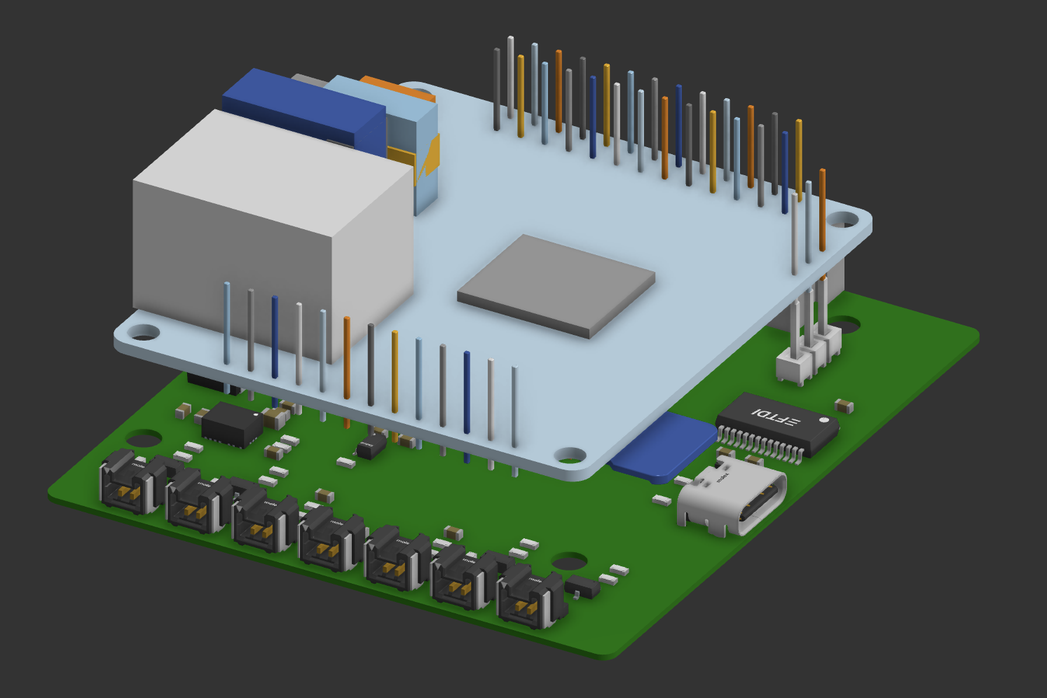
As a result, the goal for MY26 was to incorporate increased graphics performance though the usage of a single-board computer running Linux to power the dash. Thus, we ended up with an Orange Pi Zero 3W, chosen over options such as an Android tablet or Raspberry Pi to prioritize bootspeed. The Orange Pi Zero 3W main advantage is an open-source U-Boot bootloader, allowing for the modification of the boot process to get rid of noncritical processes and peripherals and ensure the system boots in a timely manner.
Details
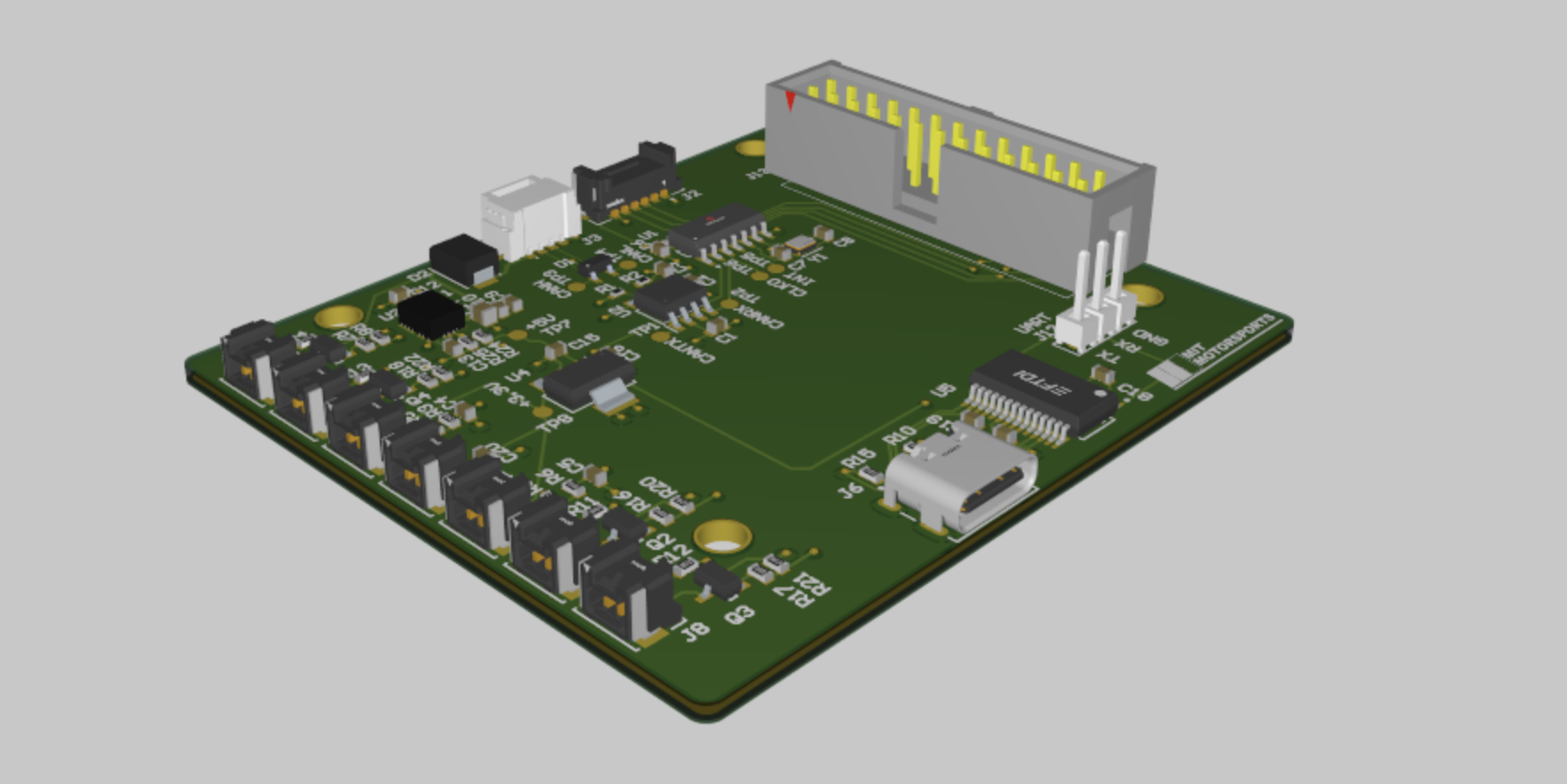
We needed to design a PCB to interface the Orange Pi with the rest of the car and the dash’s peripherals. The resulting PCB, referred to as the dash board, has a CAN controller and transceiver for communicating with the rest of the car, an SPI connection for communicating with the wheel PCB, a 24 V to 5 V regulator, and numerous connectors for interfacing with the dash’s safety buttons and LED indicators.
🏗️ 🦺 🛠️ 👷🏿 More to come as we assemble and test the board this upcoming January!